There are many projects that require an accurate 1Hz clock signal, most involving the measurement of time, or controlling something based on time. There are timers, time clocks, nixie and other real time clocks, and many others. In my case, I wanted to build a very simple frequency counter. That circuit, in essence, simply counts how many pulses happen within 1 second. To make the counter as accurate as possible I needed my 1 second counting period to be as accurate as possible.
There are many ways to generate a 1Hz signal. Probably the most common is to use an NE555 timer circuit set up for 1Hz, but there are problems with that approach. The resistors and capacitors use to set the frequency are not all that accurate, and they drift with temperature. Actually the 555 Chip itself can drift with temperature.
Another tactic is to extract the 60Hz signal from the AC power line and divide it down to 1Hz. Aside from the hazards of working with high voltage AC, this ties you and your project to a wall socket. My project, as well as many many others, need to be portable and battery operated so this won't do.
A far less common approach is to use a GPS receiver. Most GPS modules actually have a 1Hz output derived from the signal received from the satellites so using it is simple. What's more the 1Hz signal is insanely accurate, being based on atomic clocks run by the government. The down side is that this is a fairly expensive approach. What's more, it depends on having its antenna positioned so that it can get a usable signal from the satellites.
Since just about every wrist watch and cheap wall clock obviously has a very accurate time base, we should be able to take their approach to get our signal, and that's just what we're going to do.
In principal this circuit is extremely simple. You build a crystal oscillator, and then you divide its output down to 1Hz. The crystal we're going to use here run at 32.768 KHz ( 32768 Hz ). These are commonly called clock, or watch crystals. The significance of the value is that you can successively divide 32768 by 2 and eventually you will get to 1. There are other values that will do this (all multiples of 32768), but this value is very common. That means the crystal is cheap and easy to find.
Now we need to divide it down. From the table to the right you can see that we need 15 stages of divide-by-two to get our 32.768KHz down to 1Hz. Since divide-by-two is actually a flip-flop, and flip-flops come two to a chip, that means that we'll need 8 flip-flop chips to do all the division (leaving one left over flip-flop). 8 chips means that our circuit will take up a lot of space, and waste a whole lot of power. Luckily there is an easier way.
There is a class of CMOS ICs called Frequency Dividers. In essence, they are a long string of flip-flops in a single package. This greatly reduces board space and power consumption. The specific divider chip we're going to use here is the CD4060. This is a 14-stage divider however only 10 of the divider stages are brought out to pin on the chip. One of the benefits of this chip is that it contains the circuitry needed to drive the crystal directly. All we'll need to do is add a couple of capacitors and resistors to make it run.
You can get the data sheet for the CD4060 in the PDF file for this project, or download it from
here.
|
| STAGE | ACTION | FREQUENCY |
|---|
| 0 | Crystal out | 32768 Hz |
| 1 | Divide by 2 | 16384 Hz |
| 2 | Divide by 2 | 8192 Hz |
| 3 | Divide by 2 | 4096 Hz |
| 4 | Divide by 2 | 2048 Hz |
| 5 | Divide by 2 | 1024 Hz |
| 6 | Divide by 2 | 512 Hz |
| 7 | Divide by 2 | 256 Hz |
| 8 | Divide by 2 | 128 Hz |
| 9 | Divide by 2 | 64 Hz |
| 10 | Divide by 2 | 32 Hz |
| 11 | Divide by 2 | 16 Hz |
| 12 | Divide by 2 | 8 Hz |
| 13 | Divide by 2 | 4 Hz |
| 14 | Divide by 2 | 2 Hz |
| 15 | Divide by 2 | 1 Hz |
|
About the only drawback to the CD4060 is that fact that its final output is not the 1Hz that we're looking for, its actually 2Hz. That means that we'll have to add one more stage of division to the chain to get our 1Hz output.
| CD4060 Block Diagram |
|---|
| | | | | | | |
2048 Hz | |
1024 Hz | |
512 Hz | |
256 Hz | |
128 Hz | |
64 Hz | |
32 Hz | |
| |
8
Hz | |
4
Hz | |
2
Hz | |
| | | | | | | |
(7) | |
(5) | |
(4) | |
(6) | |
(14) | |
(13) | |
(15) | |
| |
(1) | |
(2) | |
(3) | |
| | | | | | | |
 | |
| |
| |
| |
| |
| |
| |
| |
| |
| |
| |
32.768
KHz |
 |
FLIP
FLOP
|
|
FLIP
FLOP
|
|
FLIP
FLOP
|
|
FLIP
FLOP
|
|
FLIP
FLOP
|
|
FLIP
FLOP
|
|
FLIP
FLOP
|
|
FLIP
FLOP
|
|
FLIP
FLOP
|
|
FLIP
FLOP
|
|
FLIP
FLOP
|
|
FLIP
FLOP
|
|
FLIP
FLOP
|
|
FLIP
FLOP
|
|
That's actually pretty easy, we'll just add one of the flip-flop chips we were talking about above. Specifically, a CD4027 CMOS Dual J-K Master-Slave Flip-Flop. Since we only need one more stage of division we're left with a spare flip-flop, which is a bonus. A 1Hz clock signal is HIGH for a half of a second, and LOW for a half of a second. For many timing applications, like my frequency counter, you actually need a signal that is HIGH for a whole second (so you can count pulses for exactly one second). So simply take the 1Hz signal and feed it into the spare flip-flop. The output of that flip-flop will be 0.5Hz, or HIGH for one second, and LOW for one second.
You can get the data sheet for the CD4027 in the PDF file for this project, or download it from
here.
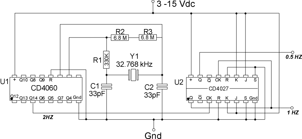
So, let's get to the final circuit...
| Designator | Component |
|---|
| U1 | CD4060 FREQUENCY DIVIDER |
| U2 | CD4027 DUAL FLIP-FLOP |
| R1 | 330K Ohm Resistor |
| R2, 3 | 6.8 Meg Ohm Resistor |
| C1, 2 | 33pF Capacitor |
| Y1 | 32.768 KHz Crystal |
| 
|
1Hz Time base Schematic
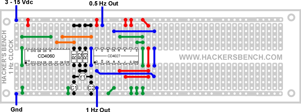
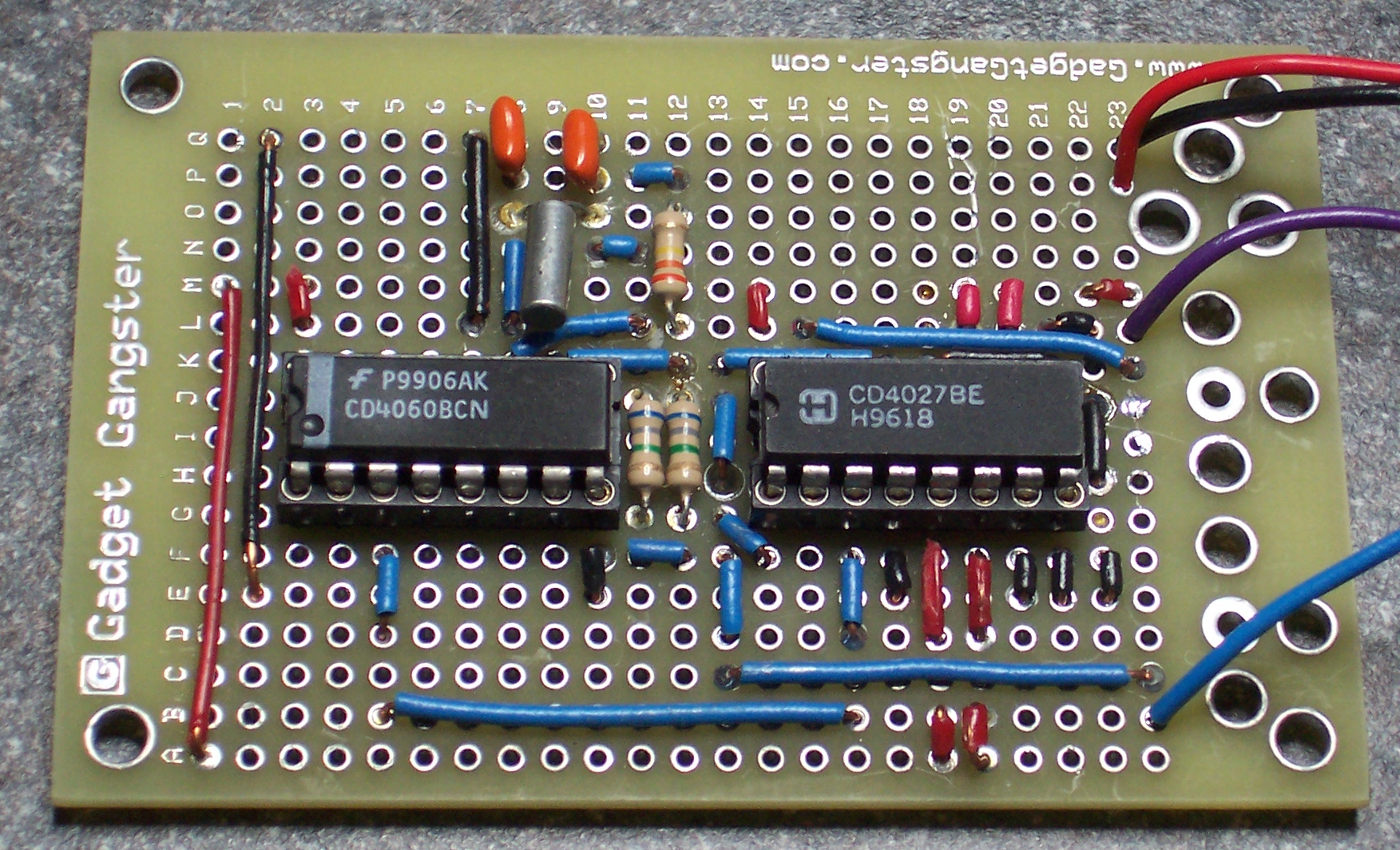
1Hz Time Base Layout, Standard Radio Shack style protoboard.
1Hz Time Base Layout, Gadget Gangster style protoboard.
 |

Questions and comments? You can find me on Twitter.
or Email me at JohnS_AZ (at) gmail |
| |
|
|