The $3 Sprinkler Timer
June, 2007


 A few years ago we built a large cover over our back deck, and shortly thereafter put up a few hanging baskets for flowers. Here (in Arizona) the summers are hot enough that you have to water the baskets at least twice a day to keep the flowers alive. The problem: I forget. Miss watering for one day and there are three hanging baskets of dead and dried flowers. Trust me, I've got three years of dead daiseys under my belt here, and Lisa doesn't let me forget it. Obviously we need an automatic sprinkler system.
I have in-ground sprinklers all over the place and maintaining them for the past 10 years has left me with a good assortment of PVC pipe and fitting so I didn't have to buy any of that, and I had a spare electric valve. Since all of the circuits in the two existing sprinkler timers were in use I needed another timer. A little shopping revealed that there is no such thing as a 1-circuit timer. The smallest are 4-circuit, and the cheapest I found was about $35. Now, $35 isn't all THAT much, but I hated to buy the 4-circuit timer and leave three of the circuits unused. Besides, I had a feeling I could do it all MUCH cheaper.
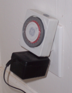
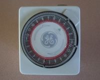 I found these timers at dollar store a few years ago. I wanted two of them to turn my christmas lights on and off, but since they were only $2 each I bought the six that they had left, and have had the extra four stored away since then. Knowing I was going to write this I've kept an eye out for them the past few weeks and have found timers like these in the dollar stores for a few bucks, and frequently in thrift stores for as little as one dollar. You can also find them online for about 5 bucks, and even cheaper on eBay (see ad bar at the right). This timer has 4 tabs per hour covering 24 hours in a day. That means that the timer turns something on and off in increments of 15 minutes. You could conceivably turn something on and off 48 times a day. Using this timer watering my hanging baskets three times a day is easy.
The timer controls a 115VAC outlet molded into it's case, and the irrigation valves that I have are all operated by 24VAC. All I needed was a power supply that takes 115VAC and outputs 24VAC. The answer is obvious. I'm sure each and every one of you has a couple dozen of these plugged in around your house.
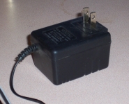
I found the "wall wart" transformer at a Salvation Army store hanging on a pegboard with about 200 other transformers. It took me about 10 minutes to find one that output 24 volts, and it only cost me $0.99. Yup, ninety nine cents ( -ALWAYS- hit the thrift stores on their half-off days). You can also find them for a bit more online here or here or here. I had no idea how much current a sprinkler valve draws, but both of my existing sprinkler systems have wallwarts that are rated for 300mA at 26Vac so I chose one with the same specs.

You could use just a bare transformer if you can't find a powersupply. Just get the same specs: 115V in and 24V out at 300mA or better. You can get one for 4 bucks here. Now, here's how it all goes together ( this is so easy it's almost silly to write it down, but here goes):
Step 1 : Wire the wallwart to the sprinkler valve.
Step 2 : Plug wallwart into timer module.
Step 3 : Plug timer into wall outlet.
Step 4 : Set the time on the timer, and flip the tabs to make it water when you want.
DONE!
|
So, $2.00 for the timer and $1.00 for the transformer. For $3.00 I have a programmable sprinkler timer that has even more programming flexibility than the regular irrigation timers ( most commercial sprinkler timers only let you cycle a zone once or twice per day).
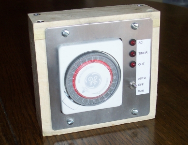
That's all there is to it... Well, almost ... While the timer/transformer works great, it looks kind of klugey. Worse, there are no lights or switches!!!
Seriously, I just plugged it all together and ran it for a couple months and while it ran great there were a couple of shortcomings. If you want to manually turn the water on you have to fuss around with the little tabs. And if you need to turn it off all you can do is unplug the whole thing, and then reset the time when you plug it back in. So, the mission is to:
Put the whole thing in a decent enclosure.
Add a manual "ON" switch.
Add a manual "OFF" switch.
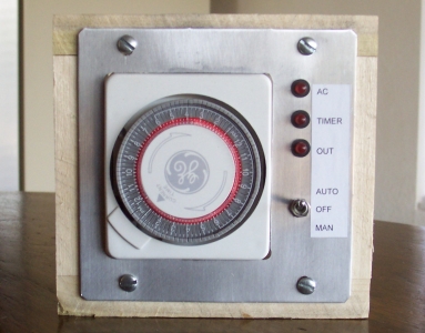
It might look like I want a little "over the top" with this but I had the aluminum plate left over from an earlier project. I cut the plate to size and filed the edges smooth. Then I milled out an opening the same size as the timer and drilled one hole for the toggle switch. I built a simple wooden box but you could use just about any kind of enclosure for this. As always, free or cheap is best, BUT REMEMBER... we're messing with line voltage here and you can kill your self fairly easily. If you're unsure, don't do it, and get someone to help you who knows what they're doing. While I'm thinking about it, here's the legal CYA: If you try to do what I've said here, you will be seriously injured or killed, so don't do it.
So here is the circuit. This is for the "fancy" version. The "just plug it together" circuit is too simple to draw.

I'm going to say it again: If you are not positive how to wire that toggle switch, please find someone who is!
Power comes in on the 3-wire line cord and is applied to the timer, and to the top two contacts of the DPDT toggle switch. The green ground wire is attached to the aluminum panel. To keep things simple I just soldered the power wires of the line cord to the plug prongs of the timer, and then soldered two more wires to to the prongs to lead to the switch, finally protecting each prong with heat shrink tubing. I then found a 2-wire line cord (from a dead curling iron Lisa was throwing away). I attached the wires to the bottom contacts of the toggle switch and plugged its plug end into the socket of the timer. And finally, using some of the left over line cord I ran wires from the center toggle switch terminals and soldered them to the prongs of the wall wart, also insulating them with heat shrink tubing.
Since both the timer module and the wall transformer are U.L. rated, and we're not really modifying them in any way, I didn't see the need to add any fuses or circuit breakers. I did, however, make sure this is all plugged into a G.F.I. outlet.
The toggle switch is of the "center off" variety, meaning that it has three positions: Up, down, and center. When it's in the center position nothing is connected. So, when the toggle switch is in the up position, the timer output is connected to the wall wart and the timer will turn the water on and off. When the switch is in the middle position nothing is connected, so the water will never turn on. And when the switch is in the down position AC power is applied directly to the wall wart (bypassing the timer) and the water will immediately turn on.
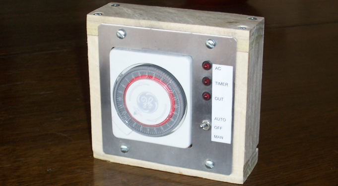
You could easily live without lights on this, but I have hundreds of LED around, and they could come in handy if something ever goes wrong. I drilled three more holes in the case for the LEDs. One is connected directly to the incomming AC power. The second is connected to the output of the timer, and the third is connected to the output of the wall wart. If the system ever fails you can just look at the panel. If the first LED is lit, there IS power available to the system. If you actuate the timer and the second LED never turns on, the timer has failed. If the second LED turns on but the third doesn't, the wall wart has failed. And if all three light up, either the valve or its wiring has gone bad.
John |
from: SCOOBYDOO (posted to the LifeHacker.com website) on 15 July 2007 : $3 is of course bogus. It CAN be $3 if you find the parts at a thrift store, but he also doesn't take into account the cost of the housing, wiring or the most important part: the valve. He had a spare valve lying around, so no wonder he didn't include that in the pricing.
Hmmm. First off, if the project included the valve it would be a sprinkler SYSTEM, not a sprinkler TIMER as it's titled. And you're right, the price does not include the housing, wiring, etc., but then the root of the project is plugging a wallwart into a timer and that would make for a pretty darn boring article. But, to completely address your comment: The wood for the housing was a piece of scrap I dug out from under my table saw, I cut the aluminum plate out of the chassis of an old rack-mounted telemetry decomutator that I disemboweled quite a while ago (got a totally cool LCD display from that), and the toggle switch and LEDs were harvested from some other piece of scrap.
So, for *ME*, the cost of the final verson was actually $3.00 as stated. Granted, if you go to Home Depot and buy a stick of red oak and a sheet of 3/16 aluminum, it's gonna cost a bit more.
Thanks for the feedback!
from: MOE52 (via email) on 14 July 2007 : The one thing I would add is a fuse -- especially if you're posting plans for people to follow. Probably 50-100 mA (in series with the AC plug) would be right.
Hi Moe. Several of the folks on LifeHacker.com expressed the same thing. Of course, you certainly could add a fuse to the project but I don't think it's necessary. The wall-wart is internally fused both for current and over-temp as all UL listed ones are. If the wallwart fails, it's no different than if it failed while powering your cordless phone and plugged in in your kitchen. Adding a fuse in the high voltage section of the circuit wouldn't hurt anything, but I don't think it adds much protection. If you managed to get a dead short in there somehow the circuit breaker in the house wiring would kill the juice. And if you managed to get your fingers across the AC (no sarcasm at all, I've done this plenty of times!) the GFI in the outlet will kill it.
This did, however, get me thinking. The RainBird timer that runs a bunch of my other sprinklers DOES have a fuse in it. I took the thing apart this morning and reverse-engineered the ciruit a bit. I found that the fuse is inline with the power used to actuate the solenoid valves. I'm guessing this is to make sure that a dead-short out there in the wiring doesn't 'smoke' the power supply. Given the squirrels I'm dealing with in my back yard, and their nasty habbit of chewing the insulation off of any wire they can get at, I've decided that it's a good idea!
I'll edit the schematic and add come copy soon. Thanks!
from: saimhe (via the Make blog) on 12 July 2007 : I always believed that in order to use a LED with AC, a regular diode should be connected in parallel (and backwards, of course) to minimize the reverse voltage. The author does just that in a 24 V circuit, but connects the protection diode serially in a 110 V circuit. Why?
Hi Saimhe. I've always thought the same thing, then I came across this. I didn't quite get it, but I wired it up and my test circuit ran fine for weeks, and nothing got hot. I like this configuration better because it's easier to wire it together and stuff the whole thing in a piece of heat-shrink tubing.
Since your question made me go look up the original schematic I noticed that I forgot to note that the resistors are 1W. I've changed the schematic on the page. Thanks!
 
|
|
|
|


