So I've been working on my Hackaday Prize entry which involves using a very sensitive magnetic sensor to detect the spinning of my water meter. Once I determined that the sensor did indeed work, it was time to sit down and work on the software. This required editing the code, flashing it into the microcontroller chip, hauling the sensor outside to the meter, hauling it back inside to my shop, and repeat. It got pretty annoying pretty fast. I decided I needed some sort of water meter simulator so that I could test my code here on the bench.
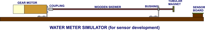
The simulator is pretty simple. It's just a small surplus gear motor that spins a magnet in proximity to the sensor. The motor drives a long wooden dowel with the magnet attached to the other end to ensure that the sensor wasn't picking up fields from the motor itself, thus skewing my readings. I tried powering the motor from a variable bench power supply but found that the motor would stall at low voltages and I couldn't run it slowly enough to simulate very low flow rates through the water meter. I then decided I needed a real motor speed controller for the setup, and luckily that's pretty east to build.
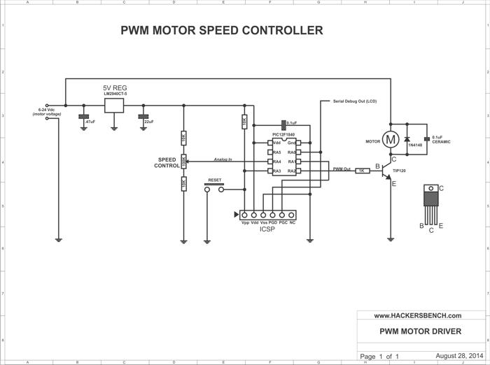
(click on this image for a clearer, printable version of this schematic)
The circuit accepts 6 volts DC (the max voltage for my motor) and supplies that directly to the motor, and to an LM2940CT-5.0 5 volt voltage regulator. The regulator provides the proper voltage for the PIC12F1840 microcontroller that will be generating the PWM signal to drive the motor. While I use a Microchip 8-pin microcontroller in this instance, you could easily use an AVR or other chip, or even a board like an Arduino. The microcontroller simply accepts a variable analog control voltage, and sets the PWM duty cycle accordingly. The higher the input voltage, the higher the PWM duty cycle, and the faster the motor will turn. The PIC12F1840 makes this very easy because the little 8-pin part has both an internal ADC (analog to digital converter) and internal hardware to generate the PWM signal, saving me from writing a lot of code to generate PWM manually.
In the schematic, resistors R1 and R2 along with potentiometer R3 form a variable voltage divider. R1 and R2 keep the voltage output from the pot away from ground and Vcc voltage levels, making the voltage range of the pot from about 0.25 volts to 4.75 volts (we'll measure the actual voltage later). The wiper from the pot sends the variable control voltage to pin 3 of the microcontroller, one of the analog input pins on this PIC.
In software, the PIC reads the voltage input on pin 3, scales that value such that it matches the range of the PWM generator, and then applies that number to the internal PWM register that controls its duty cycle. The PWM signal is output on pin 5, and it's duty cycle will vary from 0% (motor off) to 100% (motor on full). The PWM signal is sent through resistor R4 to the base of T1, a TIP120 darlington power transistor. The TIP120 essentially acts like a switch, allowing or disallowing power to flow through the motor. Since whenever the TIP120 is turned on the motor receives the full 12 volts from the power supply we won't have the problem of the motor stalling at low speeds.
You will also note that there is diode D1 and capacitor C3 wired across the motor. Whenever the motor is turned off there is a large negative voltage created by the magnetic fields of the motor windings collapsing. D1 absorbs that negative voltage thus protecting the transistor T1. Another issue with DC motors is that they can generate a lot of electrical noise (voltage spikes). This noise might travel back up the power line and cause problems for both the voltage regulator and the PIC microcontroller. capacitor C3 absorbs the bulk of that noise and protects the rest of the circuit.
You will also note that pin 7 of the microcontroller is labeled as "Serial Debug Out". Although when this circuit is completed there will be no connection to a display, having one during the programming phase of the design will be handy. For example: Consider the voltage divider made up of R1, 2, and 3. The value of any resistor (or pot) is not exact. There is some variability from one part to another of the exact same value. This means that we can not exactly predict what the voltage range on the output of the pot is going to be until we build it. It would be very handy to add a display so that early in the programming phase of the project we can read the output of the ADC across the range of the pot and adjust our software accordingly. We come across a similar issue with the PWM signal. We know that at 0% duty cycle the motor isn't going to turn, but it's probably not going to turn at 1% duty cycle either. There will be some minimum value to make the motor turn. Having a display would allow us to figure out what that value is, and scale things in software so that there isn't a large dead band at the lower end of the pot position. The "Serial Debug Out" provides that display.
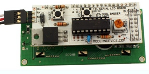
LCD Backpack from Modern Device |
Probably one of the most valuable tools I have for microcontroller development is a simple LCD display module (I prefer a 4 line by 20 character display) and a serial backpack. The backpack I prefer is the
LCD117 Serial LCD Kit from the
Modern Device company. I actually keep a few of these around since I will often use them in final versions of microcontroller projects that require a display. Using the backpack required only a single serial pin on the microcontroller, and I/O pins can often be in very short supply. With this I can set one pin of the microcontroller to be a serial output, and send measurements or debug messages to the display while developing my code. Once complete, the display and backpack are removed from the circuit and the software driving the display is removed from the source code. Yes, many IDEs allow you to do pretty much the same thing back through the programming cable to a window on your computer, but I find this approach to be much simpler and faster, and it wont clutter up my computer screen with additional windows. You can see the debug monitor in action in these photos:
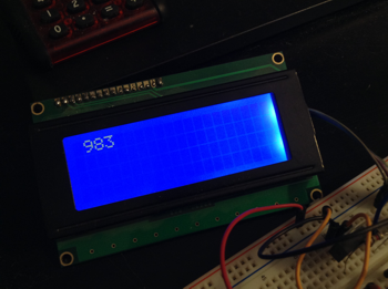 |  |
| This is the display when running the first program listed below. It is displaying the result of the analog to digital conversion, and thus the setting of the potentiometer. |
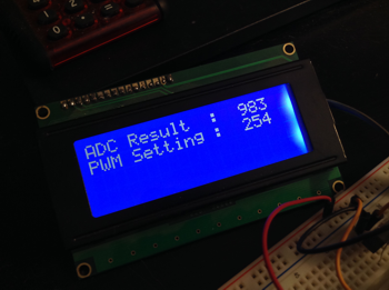
This is the display when running the second program listed below. The display is showing the result of the A/D conversion, and the scaled output to the PWM control register. This allowed me to 'tune' the system for the response I wanted. |
Construction |
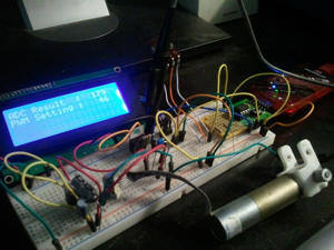
My circuit on the breadboard |
|
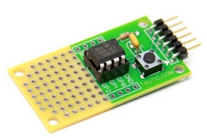
TAUTIC ELECTRONICS 8-Pin PIC Dev Board |
|
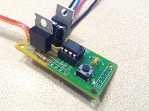
PWM circuit built on TAUTIC dev board |
|
|
As always I built this circuit up and a standard protoboard to confirm that everything works as I had predicted. Once that is done I build the circuit up in a more permanent soldered form on a breadboard. Since little 8-pin microcontroller projects usually have very little external circuitry, my absolute favorite breadboard to use is the 8 Pin PIC Development Kit available from TAUTIC Electronics. The board provides the microcontroller, the reset circuitry and reset switch, and a ready made connector for the Microchip PICKit 3 programmer. Yeah, sure, you could wire that all up yourself on a blank protoboard, but using this board saves a
bunch of time, and the end result is a much cleaner finished product. Note that the schematic above includes the circuitry and wiring that's included with TAUTIC's board so you can wire it all up yourself if you choose.
|
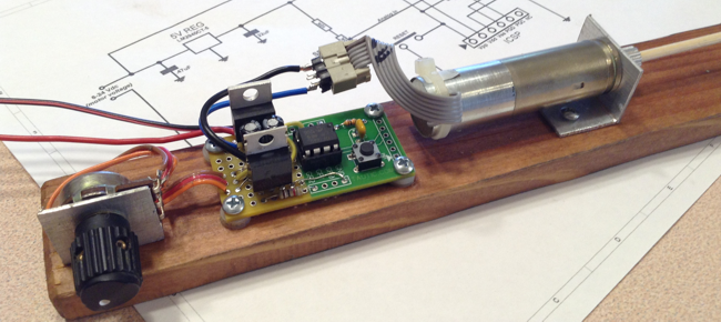
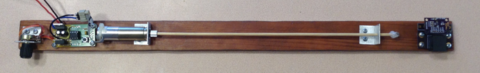
The completed board installed on my test rig |
|
|
Additional Notes |
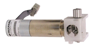
The Faulhaber motor used in my simulator |
The motor I used is one I had laying around my shop. It's a Faulhaber 1524E006S123 and is available from quite a few electronics surplus suppliers at a fair price. I found a lot of information about this motor on this page of the Robot Room website.
|
|
Source Code Listings
Here is the PIC12F1840 source code I used to determine the range of the voltage divider and pot ...
//       PWM MOTOR CONTROLLER : RESISTOR DIVIDER MEASUREMENT
//
//   written by John Schuch (aka HackersBench.com) Aug 29, 2014
//   This software is released as PUBLIC DOMAIN. No rights reserved
//
//   This program simply measures the voltage from the pot on the
//   PWM motor speed controller and displays it on the LCD display.
//   These values will then be used in the final program for the
//   controller. Visit www.hackersbench.com for full project details
//

#include <stdio.h>
#include <conio.h>
#include <stdlib.h>
#include <string.h>
#include <xc.h>
#include <pic12LF1840.h>
#define _XTAL_FREQ  8000000      //tell compiler that the clock is 8 MHz

#pragma config MCLRE=ON          // Reset pin enabled
#pragma config CP=OFF            // Code protection off
#pragma config WDTE=OFF          // Watch Dog Timer disabled
#pragma config FOSC=INTOSC       // Set to internal clock

void putch(char c);              // Variable used by serial port routines

void main() {
    OSCCON  = 0b01110010;     //Set internal clock, 8MHz
    INTCON  = 0b00000000;     //Disable all interrupts
    ANSELA  = 0b00000000;     //Disable all analog input
    WPUA    = 0b00000000;     //Disable all internal weak pull ups
    TRISA   = 0b00001010;     //Configure pins for input(1)/output(0)


    // CONFIGURE SERIAL PORT
    // See page 247 of PIC12(L)F1840 Rev E datasheet for a complete
    // description of the EUSART (serial port) register settings.

    APFCON  = 0b10000000;     //Place RX on RA5 (pin 2) and TX on RA0 (pin 7)
    TXSTA   = 0b00101000;     //Ext clock, 8 bit, xmit enabled, async mode
    RCSTA   = 0b10010000;     //Port enabled, 8 bit, rcv enabled
    BAUDCON = 0b00000000;     //Non-inverted data, 8 bit BRG
    SPBRGH  = 0;              //High byte of BRG control
    SPBRGL  = 12;             //Low byte of BRG control (9600 baud)


    // Set up LCD display
    // Display uses an LCD117 serial backpack from Modern Devices.
    // The serial backpack is kind of slow so the delays keep the
    // processor from over running the input buffer.
    // Visit http://moderndevice.com/product/lcd117-serial-lcd-kit/
    // for full details on this backpack.

    __delay_ms(4000);          // Wait 4 seconds for backpack to boot
    printf("?G420");           // Display area = 4 X 20 chars
    __delay_ms(5);
    printf("?f");              // Clear screen
    __delay_ms(5);
    printf("?c0");             // Cursor off
    __delay_ms(5);
    printf("?a");              // Home cursor

    // Set up Analog/Digital Converter of the 12F1840
    TRISAbits.TRISA4 = 1;      // Set RA4 (pin 3) as an input
    ANSELAbits.ANSA4 = 1;      // Set RA4 (pin 3) as an analog input
    ADCON0 = 0b00001101;       // Set ADC to read AN3 (RA4), ADC enabled
    ADCON1 = 0b10000000;       // Right justified, Fosc/2, Vref=Vdd
    unsigned int ADCresult;    // Variable to hold ADC result

        /* MAIN LOOP */
    while (1) {                // Loop forever

    ADCON0bits.GO = 1;         // Start analog conversion
    while (ADCON0bits.GO) {}   // Wait for conversion to finish
    ADCresult = ADRESH * 256;  // Read 2 MSBs of conversion
    ADCresult += ADRESL;       // Add the 8 LSBs of conversion
    char buf[10];              // Buffer to hold ADC reading as ASCII
    itoa(buf, ADCresult, 10);  // Convert reading to ASCII
    printf("?a");              // Home cursor
    if (ADCresult < 1000) { printf(" "); } // pad blank spaces
    if (ADCresult < 100)  { printf(" "); } // pad blank spaces
    if (ADCresult < 10)   { printf(" "); } // pad blank spaces
    printf(buf);               // Send result to LCD display

    } // end of while(1)
} // end of main()

void putch(char data) {      // This code stub is required by the
while( ! TXIF)               // USART library
continue;
TXREG = data;
__delay_ms(5);
}
|
Here is the PIC12F1840 source code I used to determine the low limit of PWM duty cycle driving the motor...
//       PWM MOTOR CONTROLLER : Scaling Conversion Test
//
//   written by John Schuch (aka HackersBench.com) Aug 29, 2014
//   This software is released as PUBLIC DOMAIN. No rights reserved
//
//   This program reads the ADC, does the scaling conversion for the
//   PWM value, sets the PWM, and displays the values on the LCD.
//   This allows me to tune the scaling conversion such that one
//   extreme of the pot sets the PWM to full on, and the other sets
//   the PWM for the minimum value that will move the motor.


#include <stdio.h>
#include <conio.h>
#include <stdlib.h>
#include <string.h>
#include <xc.h>
#include <pic12LF1840.h>
#define _XTAL_FREQ  8000000      //tell compiler that the clock is 8 MHz

#pragma config MCLRE=ON          // Reset pin enabled
#pragma config CP=OFF            // Code protection off
#pragma config WDTE=OFF          // Watch Dog Timer disabled
#pragma config FOSC=INTOSC       // Set to internal clock

void putch(char c);              // Variable used by serial port routines

void main() {
    OSCCON  = 0b01110010;     //Set internal clock, 8MHz
    INTCON  = 0b00000000;     //Disable all interrupts
    ANSELA  = 0b00000000;     //Disable all analog input
    WPUA    = 0b00000000;     //Disable all internal weak pull ups
    TRISA   = 0b00001010;     //Configure pins for input(1)/output(0)

    // CONFIGURE SERIAL PORT
    // See page 247 of PIC12(L)F1840 Rev E datasheet for a complete
    // description of the EUSART (serial port) register settings.

    APFCON  = 0b10000000;     //Place RX on RA5 (pin 2) and TX on RA0 (pin 7)
    TXSTA   = 0b00101000;     //Ext clock, 8 bit, xmit enabled, async mode
    RCSTA   = 0b10010000;     //Port enabled, 8 bit, rcv enabled
    BAUDCON = 0b00000000;     //Non-inverted data, 8 bit BRG
    SPBRGH  = 0;              //High byte of BRG control
    SPBRGL  = 12;             //Low byte of BRG control (9600 baud)


    // Set up LCD display
    // Display uses an LCD117 serial backpack from Modern Devices.
    // The serial backpack is kind of slow so the delays keep the
    // processor from over running the input buffer.

    __delay_ms(4000);          // Wait 4 seconds for backpack to boot
    printf("?G420");           // Display area = 4 X 20 chars
    __delay_ms(50);
    printf("?f");              // Clear screen
    __delay_ms(50);
    printf("?c0");             // Cursor off
    __delay_ms(50);
    printf("?a");              // Move to home position
    __delay_ms(50);
    printf("ADC Result  : ");
    printf("?x00?y1");         // move to line 2
    printf("PWM Setting : ");

    // Set up Analog/Digital Converter of the 12F1840
    TRISAbits.TRISA4 = 1;      // Set RA4 (pin 3) as an input
    ANSELAbits.ANSA4 = 1;      // Set RA4 (pin 3) as an analog input
    ADCON0 = 0b00001101;       // Set ADC to read AN3 (RA4), ADC enabled
    ADCON1 = 0b10000000;       // Right justified, Fosc/2, Vref=Vdd
    unsigned int ADCresult;    // Variable to hold ADC result
    unsigned int PWMvalue;     // Variable to hold the scaled conversion

    // Set up PWM module of the 12F1840
    TRISAbits.TRISA2 = 0;      // Set RA2 (pin 5) as an output
    APFCONbits.CCP1SEL = 0;    // Send PWM to RA2 (pin 5)
    PR2      = 0b11111111;     // Set PWM period
    T2CON    = 0b00000110;     // PWM ON, Prescale clock by 16
    CCP1CON  = 0b00001100;     // PWM single outout mode, active high
    CCP1ASE  = 0b00000000;     // PWM Shutdown interaction disabled
    PWM1CON  = 0b10000000;     // PWM Autostart, no delay
    PSTR1CON = 0b00010001;     // PWM P1A enabled, PiB disabled
    CCPR1L   = 0b00000000;     // PWM duty cycle (start at 0%)

        /* MAIN LOOP */
    while (1) {                         //Loop forever

    // Do conversion and store result in ADCresult
    ADCON0bits.GO = 1;         // Start analog conversion
    while (ADCON0bits.GO) {}   // Wait for conversion to finish
    ADCresult = ADRESH * 256;  // Read 2 MSBs of conversion
    ADCresult += ADRESL;       // Add the 8 LSBs of conversion

    // Display ADC result on LCD screen
    char buf[10];              // Buffer to hold ASCII conversion
    itoa(buf, ADCresult, 10);  // Convert reading to ASCII
    printf("?x14?y0");         // Position cursor on LCD display
    if (ADCresult < 1000) { printf(" "); } // Pad for leading zeros
    if (ADCresult < 100)  { printf(" "); } // Pad for leading zeros
    if (ADCresult < 10)   { printf(" "); } // Pad for leading zeros
    printf(buf);               // Display result

    // Scale ADC result to PWM value
    PWMvalue = ADCresult*.259;     //Scale ADC result to PWM value

    // Display scaling result on LCD screen
    itoa(buf, abs(PWMvalue), 10);  // Convert reading to ASCII
    printf("?x14?y1");         // Position cursor on LCD display
    if (PWMvalue < 1000) { printf(" "); } // Pad for leading zeros
    if (PWMvalue < 100)  { printf(" "); } // Pad for leading zeros
    if (PWMvalue < 10)   { printf(" "); } // Pad for leading zeros
    printf(buf);               // Display result
    CCPR1L = (PWMvalue);       //Write PWM value to PWM register

    } // end of while(1)
} // end of main()

void putch(char data) {      // This code stub is required by the
while( ! TXIF)               // USART library
continue;
TXREG = data;
__delay_ms(5);
}
|
Here is the final version of the PIC12F1840 source code...
//       PWM MOTOR CONTROLLER : Final Code
//
//   written by John Schuch (aka HackersBench.com) Aug 29, 2014
//   This software is released as PUBLIC DOMAIN. No rights reserved
//
//   This program reads the position of a potentiometer through an
//   ADC conversion, and then scales that result so that it can be
//   written to the PWM control register. The PWM output from the
//   microcontroller as applied to a TIP120 transistor which controls
//   the motor speed. For complete details on this project please
//   visit www.hackersbench.com
//
//   Target microcontroller        :  PIC12F1840
//   Compiler                      :  MPIDE / XC8 V 1.21
//   Programmer                    :  Microchip PICKit 3
//

#include <xc.h>
#include <pic12F1840.h>
#define _XTAL_FREQ  8000000      //tell compiler that the clock is 8 MHz

#pragma config MCLRE=ON          // Reset pin enabled
#pragma config CP=OFF            // Code protection off
#pragma config WDTE=OFF          // Watch Dog Timer disabled
#pragma config FOSC=INTOSC       // Set to internal clock

void main() {
    OSCCON  = 0b01110010;      // Set internal clock, 8MHz
    INTCON  = 0b00000000;      // Disable all interrupts
    ANSELA  = 0b00000000;      // Disable all analog input
    WPUA    = 0b00000000;      // Disable all internal weak pull ups
    TRISA   = 0b00001010;      // Configure pins for input(1)/output(0)

    // Set up Analog/Digital Converter of the 12F1840
    TRISAbits.TRISA4 = 1;      // Set RA4 (pin 3) as an input
    ANSELAbits.ANSA4 = 1;      // Set RA4 (pin 3) as an analog input
    ADCON0 = 0b00001101;       // Set ADC to read AN3 (RA4), ADC enabled
    ADCON1 = 0b10000000;       // Right justified, Fosc/2, Vref=Vdd
    unsigned int ADCresult;    // Variable to hold ADC result
    unsigned int PWMvalue;     // Variable to hold the scaled conversion

    // Set up PWM module of the 12F1840
    TRISAbits.TRISA2 = 0;      // Set RA2 (pin 5) as an output
    APFCONbits.CCP1SEL = 0;    // Send PWM to RA2 (pin 5)
    PR2      = 0b11111111;     // Set PWM period
    T2CON    = 0b00000110;     // PWM ON, Prescale clock by 16
    CCP1CON  = 0b00001100;     // PWM single outout mode, active high
    CCP1ASE  = 0b00000000;     // PWM Shutdown interaction disabled
    PWM1CON  = 0b10000000;     // PWM Autostart, no delay
    PSTR1CON = 0b00010001;     // PWM P1A enabled, P1B disabled
    CCPR1L   = 0b00000000;     // PWM duty cycle (start at 0%)

        /* MAIN LOOP */
    while (1) {                         //Loop forever

    // Do conversion and store result in ADCresult
    ADCON0bits.GO = 1;         //Start analog conversion
    while (ADCON0bits.GO) {}   //Wait for conversion to finish
    ADCresult = ADRESH * 256;  //Read 2 MSBs of conversion
    ADCresult += ADRESL;       //Add the 8 LSBs of conversion

        // Scale ADC result and write to PWM control register
    CCPR1L = (ADCresult*.259);     //Write scaled PWM value to register

    } // end of while(1)
} // end of main()
|
|