|
June 27, 2006 :
Motivation and First Steps
This project has two beginnings. First, some time ago I was looking for a cheap remote control that
would turn on my driveway floodlights from the car. Yea, an IR motion detector would work, and I
even tried that for a while. The problem is that we have coyotes, javalina, and other nocturnal
creatures that wander around here and I didn't want the lights to turn on automatically and scare
them off. Further, I support the folks at
Dark Sky. I started watching for old garage door remotes
but none ever crossed my path. That was about a year ago. Then a few days ago a guy named Brett
posted a question to the
Make Forums
saying he wanted to remotely turn his PC on and off. Toward that end he had bought this wireless
doorbell and wondered how to run the receiver off of the PC power supply instead of batteries. As
of this writing that conversation is ongoing, but it reminded me of my old flood light project.
So, since we needed to reverse engineer the receiver to solve Betts' issue, and it seemed like a
perfect fit for my lights, I confirmed the part number and headed off to Home Depot.
(RANDOM NOISE: I think I'm going to start shopping at Handy Andy's Hardware, or any other
small hardware stores I can find. It's not that I have a problem with the prices or products at Home Depot,
it's their "self-check-out" system. And it's not so much the systems as it's the fact that
the Home Depot closest to me very often has NO human checkers!! They make due with one clueless young
girl to monitor the machines. Now if everyone shopping there was as smart as you or I, there would be
no problems. I, however, always seem to get there the same time as the grandpa trying to figure out
how to run the machine, the clueless goon trying to take 16 sheets of plywood through, and the young
girl that managed to pick out the only 45 PVC fitting in the whole store that have unreadable barcodes.
And then there are those security anti-shoplifting tags buried inside half of the things there.
You know, the sensors at the door can see one of those things from 8 feet away. So why the
hell can't the AutoSelfCheckersFromHell machines tell that you just put one in your bag?!?!
Yea, all the alarms went off when I tried to leave the store with my doorbell. )
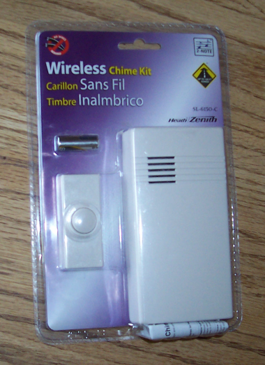
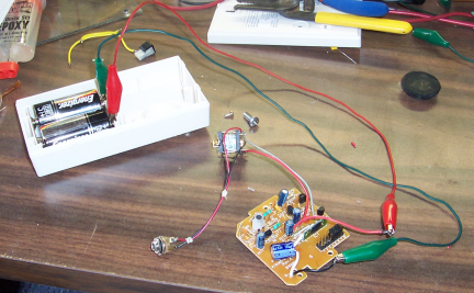
I finally got home with the doorbell and the batteries. First things first; let's make sure it works.
This is the first step because it's really really difficult to return something like this to the
store as defective AFTER you've ripped it's guts out! Batteries installed, the doorbell works as it
should. Granted, it sounds pretty crappy, but then I'm more of a 'solenoids striking huge brass chimes'
doorbell kind of guy. This thing is simple enough that my Mom could install it. Now for a range check.
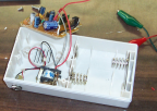
The package says that the doorbell will work with the transmitter up to 100 feet away. When I installed
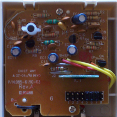
the batteries I could see that the antenna on the transmitter is a small 0.75 inch wire looped at one
end of the case, and on the receiver side, there is a small disc capacitor with one leg soldered into
the board, and the other hot-glued to the component-side of the PCB for the antenna (upper left corner
of the receiver PCB photo to the left). While it worked
great sitting on my desk with the transmitter and receiver separated about 12 inches, I was a little
suspicious of the 100 foot claim.
For the open air test I set the receiver on the patio table on my back deck. Since my lot is about 330 feet front
to back there was plenty of space. Well, reliable operation stopped at about 69 feet. From 70 to about
80 feet I could get it to work changing the orientation of the transmitter (I had been holding it as if
it were screwed to a wall). Then I placed the receiver in my kitchen and went outside my front door,
a distance of about 30 feet. The unit worked fine. Then I started walking away from the house and the
chime continued to work until I was about 50 feet away (from the transmitter, not the house). Again,
by changing the orientation of the transmitter I was able to get another 10 feet out of it. Interestingly,
the instructions for the doorbell state that installing the transmitter or receiver near metal studs, on
a metal door, or near a concrete floor can reduce the transmitters range. By my guess this rules out
about three quarters of all the homes build in the past ten years.
So the range, while not what was specified on the package, seems perfectly acceptable for a doorbell
application. This, however, is a hardware hacker project and I imagine that that limited range could become
an issue. A couple of things come to mind. First (and simplest), I have to believe that if you reworked
the antennas inside the units you could achieve a bit more range. The antenna in the receiver is a short
piece of wire, roughly vertical, and bent into a "C". The transmitter antenna is a small loop situated
horizontally. I -think- that if you rearranged the receiver antenna so that is was straight (not a "C")
and completely vertical, and then mounted the transmitter sideways so it's antenna was vertical that you
would see increased range.
The second option would be to eliminate the two internal antennas entirely and figure out what a 1/4-wave
vertical whip would be. This would CERTAINLY increase the range. I may play with that later, but the current
quest is to make this thing drive a relay instead of a speaker, and see if we can power it from a PC power
supply. So tomorrow it will be time to deal with the guts.
|
| | |

|
June 28, 2006 :
Electro-Vivisection
Last night I made a pot of coffee, stuck my copy of
Colossus
into the DVD, ( "Colossus" is in my top-10 movies for hackers and geeks. Besides, Susan Clark is kind of
sexy in a 1970's, geek-chick sort of way) and set out reverse engineering the receiver. I have a
method of reverse engineering circuit boards involving digital pictures, PhotoShop, overlays,
and CorelDraw that is probably suitable for an article all it's own. But for now suffice it to say that
by the end of the movie I had a schematic, a decent cafine buzz, and I really had to get to the bathroom.
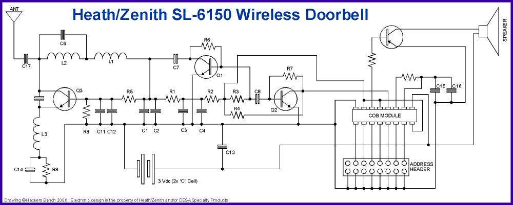
If you click on the circuit image at the left you'll open a new page with the entire schematic for the doorbell.
I've said many times that I might be sixteen kinds of geek, but RF-geek isn't one of them. Perhaps one of
my radio-gifted readers will contribute a decent discussion of what's going on in the left two-thirds of
the schematic (and maybe even tackle the antenna question). Luckily for me in the immediate project the
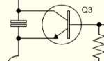
RF stuff really doesn't matter. Looking at the schematic we can see that the bulk of the parts count is for
the RF section. The transistor in the upper right is the audio amplifier, and the COB is the brains of the
thing.
(RANDOM NOISE: "COB" stands for Chip-On-Board. For a regular integrated circuit (IC), a tiny piece
of silicon is bonded to a lead frame and then encapsulated in plastic. The lead frame ultimately becomes the
ICs legs, and are soldered to traces on a circuit board. For COB, the tiny piece of silicon is bonded right
to the circuit board and traces, and then a blob of epoxy is dropped over it to protect the die and die
bonds. This saves time, space, and money for the manufacturer and you'll see this a LOT in consumer stuff
made in China. )
The address header allows the user to select one of 128 distinct addresses for the reciever and its transmitter.
This opens up the potential for some interesting remote control hacks but for now here's what we need to play with:
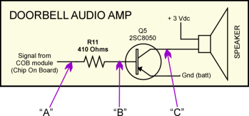
What we have is a numbingly simple audio amplifier. It kind of surprised me that there's no current limiting
through the speaker at all but then it occurred to me that it might not be an 8-ohm speaker. A quick check
with the meter and sure enough, the speaker IS 8-ohms, so it's Ohms Law time!. Current = Volts / Ohms, so
3 volts / 8 ohms = 0.375 amps, or 375ma. Power = amps X volts, so 0.375 amps times 3 volts = 1.125 watts.
Now, granted, the calculations are for DC current and the speaker is seeing some kind of pulsed or modulated
DC, driving that tiny speaker with a watt seems a little close to the limit. Since they have been selling these things for a
number of years we'll presume it's not a design flaw, and just chalk it up to 'art'. Next we need to know what sort of signals are going
through this circuit. Using an oscilloscope I'll make measurements at the three labeled points of the circuit.
But for now all I have in front of me is a meter so let's check out the power.
Powerplay
Brett wants to run this off of his PC power supply after all so we need to know
how much power (current) the receiver draws. A long time ago I made a silly little widget to make this sort of
measurement a lot easier. It is a little piece of double-sided printed circuit board material about the
size of a dime. I soldered a piece of test lead wire to each side and soldered female banana jacks to the
wires' ends. To measure the current draw of a battery powered device (like our doorbell) you simply
slide the little PCB in between two of the batteries or between the end of one battery and the spring. You
then plug your current meter into the banana jacks and away you go.
(RANDOM NOISE: By the way, this is a handy way to add remote control or timers to battery operated
devices that you do not want to physically modify. Using the same little PCB between the batteries, use a
relay to short the wires together to turn the device on or off. For example, turn off the smoke detector while
you're actively burning dinner, turn a boom-box into an alarm clock, turn on the lantern when you open the
shed doors, etc.)
With the receiver sitting idle my meter indicated a current draw of 0.22 milliamps. For comparison consider that
a regular old red LED draws 20.0 milliamps, or about 100 times as much current. 0.22 milliamps is virtually
nothing, but this is with the receiver sitting idle. What happens when someone pushes the bell?
Well, something interesting happens: When the button is pressed the receiver current jumps to a little under 10 milliamps
for about 200 to 300 milliseconds, then when it starts sounding the current jumps to about 110 milliamps. The
current fades back to it's idle level with the diminishing tone of the chime. This is just a guess, but I think
that probably the module that makes up the brains of the receiver can power-down the 'made-a-sound-like-a-chime'
part of itself, leaving only the RF section powered to conserve battery life. It would be interesting to know
how much of the power is used by the module, and how much is consumed by driving the speaker. Easy; we just
remove the speaker from the circuit and measure the current again.
Repeating the measurement with one wire to the speaker unsoldered gives us the same 0.22 milliamps idle current.
When we push the button now, however, the current jumps to about 8 milliamps and just stays there until it's done
chiming. So, bottom line (and to use conveniently rounded numbers), the receiver draws 10ma, and about 100ma is
driven through the speaker. Now, if you're really paying attention, you will have noticed that this 100ma through
the speaker doesn't jive with the ohm's law figures above. Well, this is the difference between steady DC calculations
and pulsed or modulated DC. The figures above were a guess, and having made the current readings we have real numbers so
reworking the equations gives is an average of 0.300 watts, or 300 milliwatts going through the speaker. This is a
MUCH more reasonable number. All of this doesn't necessarily mean that we can just connect a 3-volt relay where the
speaker is. Again, the signal going to the speaker isn't really DC, it's some sort of pulsed, or modulated DC shaped like
the audio of a bell ringing. So we need to know a couple of things; what does the waveform across the speaker
look like, and is there enough constant DC in it to drive a relay. We should also know how much current can be
driven through that transistor. A quick check of the
C8050
data sheet tells us that the transistor can handle up to 1.5 Amps so power handling isn't a problem. Since we
want to drive a relay, we'll have to find one rated to work at 3 volts. Running off of batteries and with a current
capacity of better than an Amp through the transistor we really don't have to worry about the current draw of the
relay. This could, however, be an issue running it inside a PC.
When the PC is on there is plenty of power available to run the receiver so turning the PC off should be easy. But when
the PC is turned off the only power available is the feeble amount available to let the power switch operate, and
possibly to keep the ethernet circuitry operating (for "Wake On Lan"). Another participant in the
Make Forum,
"Lars-Phobe", offered that the current AXT power supply spec calls for at least 10ma for the stand-by 5 volt
power, but that 720ma is recommended and that 1 to 2 amps is not uncommon. Hrmph. That's a hell of a range, anywhere
from 10ma to 2 amps! On the one hand I'm thinking that most manufacturers (I was in that field for 15 years)
take a recommended spec as the actual spec, so by Lars' number we have about a 700ma budget. But some of that
power needs to be used by the motherboard so if we can make the receiver work at 200ma or less we should be
fine. On the other hand the current spec is for current computers, and we hackers / Makers have tons of old PCs
lying around and I haven't a clue what the 1990 power supply spec was. Since I have a half dozen operating PCs
here, and some are pretty darned "vintage," I'll be doing some real-world tests.
My homework:
Scope the points on the schematic and see what the signals look like.
Read the specs on the power supplies in my PCs.
And see if I have any 3V relays in my junk pile....errrr.... Piece Parts Inventory.
| | |
|
June 29, 2006 :
Wave Riding
Well, I did find some relays buried in my inventory, I didn't read all the PC power supplies, and I did scope the
receiver board. I decided that the power could wait. Let's just get a relay working on battery power, and then we'll
deal with PC power.
| | |
|
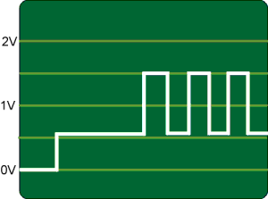 |
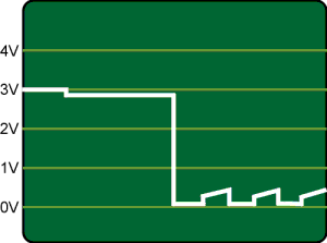
The first measurement, as marked "A" on the diagram above, is the output of the COB module to the resistor which then
drives the audio amp transistor. When the receiver first detects the signal, the output rises to about 0.60 volts.
about 300ms later the chime starts. The chime signal is a modulated squarewave that starts of oscillating between
0.60 volts and about 1.5 volts.
As the ringing fades, the amplitude of the signal drops until it is again floating at about 0.60 volts, and then
about 200ms later the output drops to zero.
I hadn't thought about it before hooking it up to the scope, but it actually cycles twice. Once for the "ding", and
once for the "dong". Since the ding is a higher frequency than the dong, there is a bit of overlap in the middle of
the complete cycle. The fact that during this overlap the output is actually to different frequencies of squarewaves,
my scope had a heck of a time syncing to the signal. |
|
The second waveform ("B") is from the other side of that resistor, and displays pretty much what we would expect. The signal
is the same as before, but the resistor is limiting the current, and therefore dropping the peak voltage to about
0.80 volts.
Since this signal is applied directly to the base of the transistor, it controls how much current flows THROUGH the
transistor. That is, controls how much current flows from the +3Vdc of the battery, through the speaker, and then
through the transistor to the negative pole of the battery. (understanding that is going to become pretty important
in a minute.
So, for example, if we lowered the value of the resistor, less voltage would be dropped across it, and our
0.80 peaks would move higher, say, to 1.20 volts. This would have the effect of making more current flow through the
transistor, and thus more current flow through the speaker. The end result? The sound from the speaker will be louder.
|  |
|
 |
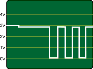
Next we look at the line between the transistor and the speaker ("C"). It's really the only one to check because the other
side of the speaker is the +3Vdc of the battery, and the other side of the transistor is the negative pole of the
battery.
When the chime isn't chiming, the transistor is turned off, and there is no current flowing through the speaker. That
means that with the chime off we see the full +3 volts on both sides of the speaker. Thus, this waveform floats at
the battery voltage. When the button is pressed, we can see about a 0.20 volt drop on this line as the voltage applied
to the base of the transistor rises to 0.60 volts (not enough to turn it fully on).
Now consider things from the point of view of the speaker. When the chime is off there is +3Vdc on BOTH of it's leads
so it "sees" 0 volts. When the chime first starts but has not start ringing yet, the speaker still has +3Vdc on one
side, but the other side has dropped to +2.80 Vdc due to that little voltage applied to the base of the transistor. With
3 volts on one side, and 2.8 volts on the other side, the speaker "sees" 0.20 volts across its terminals.
Now, when the chime starts sounding the speaker has 3 volts on one terminal, and the other terminal switches between
2.80 volts and about 1.80 volts. This means that the speaker "sees" a signal that oscillates between 0.20 volts and
about 1.20 volts. |
|
What this all boils down to is that at its maximum, there is only 1 volt across the speaker. That's plenty to make
sound come out of a speaker. It is not enough, however, to operate a relay. I guess that if you could find a relay out
there with a 1 volt coil it would work. But in all my years I've never seen one.
Now I can hear a bunch of you yelling "What about a solid state relay???". Well, one of the big selling points of solid
state relays is their complete electrical isolation between the control input and the output, and that is done using an
opto-isolator which is nothing more than an LED aimed at a photo-transistor. 1 volt still isn't enough to drive the
LED with any confidence.
What we need to do is to get that 1 volts expanded to as near 3 volts as we can.
And I already told you how to do it...
Up there ...
... where I was talking about how reducing the value of that resistor would increase the volume at the speaker? Remember?
Exactly! As we reduce the value of the resistor the transistor "opens" more allowing more current to flow, and thus
more voltage is dropped across the speaker. So what value of resistor do we want to put in there? Well, we're looking for
the maximum current through the transistor so we want as high a signal to the transistors base as possible. Since any
resistance in there is going to limit the current it's pretty obvious that to get the maximum current we won't replace
the resistor, we'll eliminate it completely.
Besides, it's a lot easier to short out the resistor that's on the board than it is to unsolder and remove it, and then
solder a replacement onto the board.
Now this isn't completely without risk. We have no way of knowing how much current we can pull out of that COB pin. I
spent a LOT of time and there are simply -NO- datasheets or other information available on the part. So, as it does with a
lot of hacking, you come to a point where you just have to cross your fingers and dive it. Heck, the absolute WORST
case is that I'll have to go brave Home Depot again and buy another $14 doorbell.
 |
|
BINGO!
As we said, with the resistor out of the circuit, the signal shown in the very first waveform above is now applied
directly to the base of the transistor, and the transistor is now toggling between fully open and fully closed. You'll
notice that the signal doesn't actually go all the way to zero. This is because even when the transistor is fully turned
on, it still drops a little voltage across it. In this case, about 0.18 volts.
So now our speaker "sees" 2.80 volts and then about 0.2 volts. This span gives us a swing of 2.6 volts which is certainly
enough to drive an LED, and is usually enough to pull in a 3 volt relay. But, we still have a problem.
It's not DC.
The power is being applied to the speaker (or our LED or relay) in pulses. In the speaker this just makes sound. In an LED,
the light actually turns on and off as fast as the signal, and this is going to cause some heartburn in a solid state
relay. And for our conventional relay, you have to average the power across time and in this case the average doesn't add
up to enough to actuate the relay.
Actually, when I tested this to get the waveform you could actually hear the chime sound coming from the relay as it struggled
to close it's contacts. It was very quiet, but I could hear it.
|  |
|
What we need is something to apply power to the relay during those gaps to bring the average up. Something that will save some
of the power when it's there, and then give it back when it's not. That is what a capacitor does.
If we place a capacitor between the speaker-transistor leg of the circuit and ground, it will (in a manner of speaking) save
up some power when the signal is there, and let it go when the signal is gone.
(Okay, okay, it's not actually applying power, it's keeping that leg of the circuit from getting back to +3 volts as
quickly as it might. Some of you can congratulate yourself on picking a nit. The rest, if you didn't understand this, don't
worry about it)
Now I would like to be able to tell you that I applied my extreme mathematical prowess to some complex formulas that I know
by heart to calculate the value of the capacitor to insert into the circuit. But that would be a lie, and life is too short
to spend any of it in my attic looking for my old high school electronics textbooks.
2.2 uF didn't work.
10uF didn't work.
Neither did 22uF or 50uF.
Then I stuck a 100uF cap in the circuit ....
 |
|
 |
There ya' go. It's not the prettiest or cleanest waveform on Earth, but it will do. With the 100uF capacitor in the circuit
pressing the doorbell button resulted in a firm, authoritative, 'CLICK' of the relay pulling in. Well, actually, it was "CLICK"
"CLICK". The relays closed twice for every press of the button.
I have to confess that I had to stop and think for a minute before I figured it out....
"Ding" ... and then ... "Dong".
Oh jeeze! Brett want's this thing to turn on his PC, and I had no clue how computers responded to double-clicks on
their power buttons. What's more, this will make my flood lights into a kind of Disco strobe light. I started trying to think
of ways to bridge the 300ms gap between clicks and then remembered the instruction sheet for the doorbell. |
The doorbell will actually play different sounds for front and back doors (if you buy a second, optional transmitter). The sound
for a back door is a single "Ding". The very last jumper position on those headers in the transmitter tells it whether it's at
a front door or a back door. I added a jumper to that position and the problem was solved. Pressing the button once clicked the
relay once. Done!
I've done all of the above testing using jumper leads and alligator clips. Let's clean that up and make the mods to the receiver.
|
| |
| | |


|
July 5, 2006 :
Hackin'
Okay, the 4th of July weekend is over. One of the kids got bit by a dog that was scared by the fireworks, plenty of sunburns
to go around, I ate too much, drank too little, and though it was a grand weekend I'm glad to be back at the bench instead
of cleaning up the pool and the backyard like I should.
To accomplish the relay mod we need to do three things ...
Short out the resistor at the audio amplifier (or replace it with a shunt).
Add a 100uF capacitor to the circuit.
Remove the speaker and replace it with a relay.
Finding the relay is probably going to be the biggest challenge. The one I have is from a lot I bought on eBay about
a year ago. I still see them from time to time, and a number of surplus electronics on-line stores have something that
will work. You're looking for a relay with a 3 Volt DC coil. Mine has a coil resistance of about 12 ohms, however
anything in that ballpark should work.
Since the receiver runs on 3 volts, just about ANY 100uF electrolytic capacitor will work. You might want to tend toward
the lower voltages (ie. 10v, 16v) because they are physically smaller.
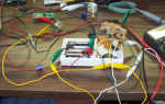
Up to this point the whole thing has been running with a bunch of alligator clip test leads connecting the receiver, the batteries,
the capacitor, and the relay. The receiver has been sitting powered since I left it about a week ago and a quick check with a
meter shows the batteries still have a full charge. I didn't expect anything else, but it's nice to confirm that my changes to
the circuitry didn't start killing the batteries.
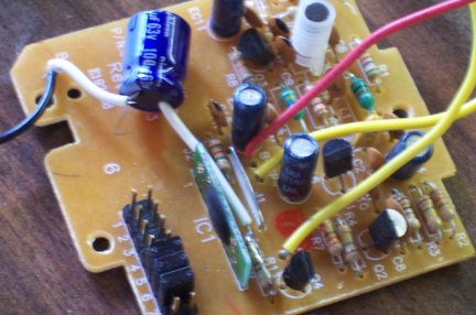
I'm just going to list the steps of the hack here as opposed to writing them all out. You can follow along with the pictures.
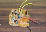
Remove the receiver board, unsoldering the wires to the battery terminals. This just makes it easier to work with the board.
Solder a wire shorting out resistor R11. This is easiest if you solder a straight piece of wire to one end, then use a fine
tipped needle-nosed pliers to bend it into shape, and then solder the other end.
Now solder one lead of the capacitor to the end of the same resistor closest to the middle of the board. I found a short
piece of scrap wire and stripped about 2 inches of it. Not for the wire, but the insulation. You can slide the insulation over the
leads of the capacitor before soldering it into place.
Solder the other lead of the capacitor to a ground point on the circuit board. I found that I could slide lead into the
same hole and along side the black wire that goes to the battery terminal.
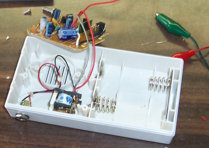
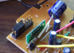
Now we need to assemble the relay. I found that originally there was not enough room for the relay inside the case of the
receiver, but then figured out that if I removed the clear case of the relay it fit just fine. Also, I like my projects to have a
finished appearance so I dig out a 1/8" mono earphone jack I had salvaged out of something ages ago. This jack will carry the relay
contacts to the outside. Solder the earphone wires to the relay contacts, and two pieces of wire to the coil leads of the relay.
Unsolder and remove the two wires on the receiver board that used to go to the speaker, and replace them with the wires
that come from the coil of the relay.
Drill a hole in the side of the case to accept the earphone jack. Install the jack, and hot-glue the relay into place in
the bottom of the receiver case.
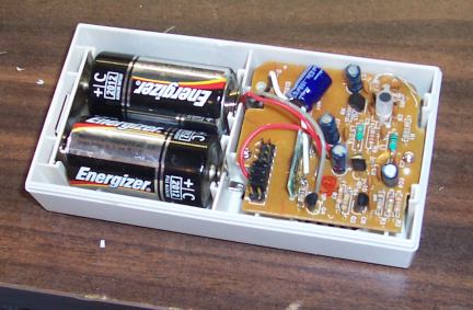
Reconnect the power wires from the receiver board to the battery terminals. I replaced the wires in mine with longer ones
just to make my life a little easier.
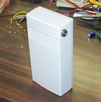
Reinstall the receiver board in the case, snap the cover on, and your done!
Just a few random notes...
At a few points through assembling this thing I stopped and reconnected everything with the test leads just to make
sure it still worked. This may seem silly to some, but doing so will help you avoid "finish line failure". That is, getting
everything assembled, putting in the batteries, snapping on the cover, and having it not work. Then you have to backtrack and
figure out at which step you made your mistake.
I thought about adding a power switch, but since the receiver will run for about a year on a pair of "C" cell batteries I saw no real
need. There is room, however, under the circuit board alongside the earphone jack to accommodate a micro-toggle switch if you want
one.
You could also add another jack for the antenna if you like. A little panel-mount BNC, "F", or banana jack should also fit under the
circuit board. If I have trouble with range I'll go ahead and add that later. But for now, 50 or 60 feet of range should do fine.
It might not be a bad idea to add a diode in parallel with the relay to shunt any back-current from the field of the relay coil collapsing when
power is removed from it. This would protect the transistor from a big reverse voltage spike. However, I didn't see anything nasty
on my scope without it, and I left it out to save current for the relay.
Another addition would be an LED indicator that lights when the relay closes. I would be concerned that the LED would draw too much of
the available current and the relay would no longer close. If you want it, give it a try. I have to leave *SOMETHING* for you folks to
figure out. 8-) Besides, the closed receiver case makes a really good resonator, and you can definitely hear the relay clicking.
I wired the earphone jack to the Normally Open (NO) contacts of the relay, so pressing the button will turn something on. You could,
alternatively, wire up the Normally Closed (NC) contacts so that pushing the button would turn something off. Better still, instead of
a mono earphone jack you could use a stereo headphone jack, bringing both the NO and NC terminals out of the receiver making the device
even more universal. What would you want to turn off remotely? Well, the stereo in our kid's car when it get's within 100 feet of our
house is the first thing that comes to mind. (grin)
Next up ... we'll get this thing running off of a PC power supply.
|
| | |
|
October 5, 2006 :
I'm back
Well it's been a crazy few months. In short, I started a new business. What it is doesn't matter to you folks,
but any of you who have gone through the ordeal know what a huge task it is. Things are settling back down now
so it's back to "work". :-)
Earlier this week I got out the doorbell and transmitter. It's been sitting since my last entry for this project
and I was pleased to find that the batteries are still good and the relay still works fine. To start to address
the power supply question, I removed the batteries and with test leads connected the battery contacts to a well
regulated bench power supply.
As you might expect, the doorbell worked just fine with the power supply set at 3 volts, the same as the batteries.
I slowly increased the voltage, a half a volt at a time, testing at each voltage. I went as far as 6 volts and it
still worked. I didn't want to go any higher than that and chance blowing the thing up. Besides, we're looking to
run it at 5 volts inside a computer, and that is a VERY well regulated power supply. So, we're golden.
Then, just for giggles, I started turning the power supply down. The receiver worked all the way down to 1.5 volts,
but relay stopped pulling in at about 2 volts. That's a good thing to know if you plan on using this mod as a
battery powered receiver. While I'm sure that in it's original state the doorbell would actually sound down to 1.5 volts,
our relay will only work down to 2. That means that while you could expect the two "C" cells to power the doorbell
for more than a year, with our relay mod the battery life will be greatly shortened.
I have some down-time early next week, and I have an idle PC sitting in my office, so I'll get this thing installed
and then update the project.
If you want to be notified when this page gets updates, send an email to:
dingdong(at)hackersbench(dot)com
If I were to rank the top evil things in the universe, the devil would be second. Spam email would be first. You can
absolutely be assured that your email address will be used for nothing else.
( By the way, third in the list is Microsoft) 8-)
|
| | |
|
October 6, 2006 :
Email Feedback
Dave B. wrote ...
Nice hack, and a very clear instructable!
One thing you mentioned was a kick-back suppression diode. A lot of relays come with the diode built-in, but if you want to add
one, place it across the relay coil, not across the 100 uF cap, as you suggested. Wire it with the cathode (+) terminal at the
+3V, the anode at the collector of the 2SC8050.
Dave
Oops. I must have been typing faster than I was thinking that day. I've
changed the 'capacitor' to 'relay' in the above text. Thanks Dave! Both
for pointing out the typo, and the compliments.
John
|
|
|